Camper Jack Controller
In Spring 2019 I took on a project to re-enable electrical actuation of a Bigfoot camper’s leveling jacks. Originally it had a wired remote that could be used to activate each of its four jacks, but it had since gone missing, meaning the owner needed to spend more than an hour each time the camper was moved.
A new controller was valued at over $700. A small price for some, or a small opportunity for a wayward engineer like myself. I’ll be honest here, I did this project mostly because I was craving the mental exercise!
How does it work?
My solution reused the existing control board, but I replaced the Z80 processor with an ESP32 SoC. I configured the ESP32 as a Wi-Fi Access Point with an on-board web server. The control interface is web-based, implemented in JavaScript and HTML. So you can control it with your phone, your kindle, your computer, baby monitor, fit bit, smart-thing, whatever. Your baby could control this thing.

The Camper
This 2003 Bigfoot Camper originally had a wired remote controller for its stabilizer jacks, which could be used to lift, lower, and level the camper on and off of a pickup truck.
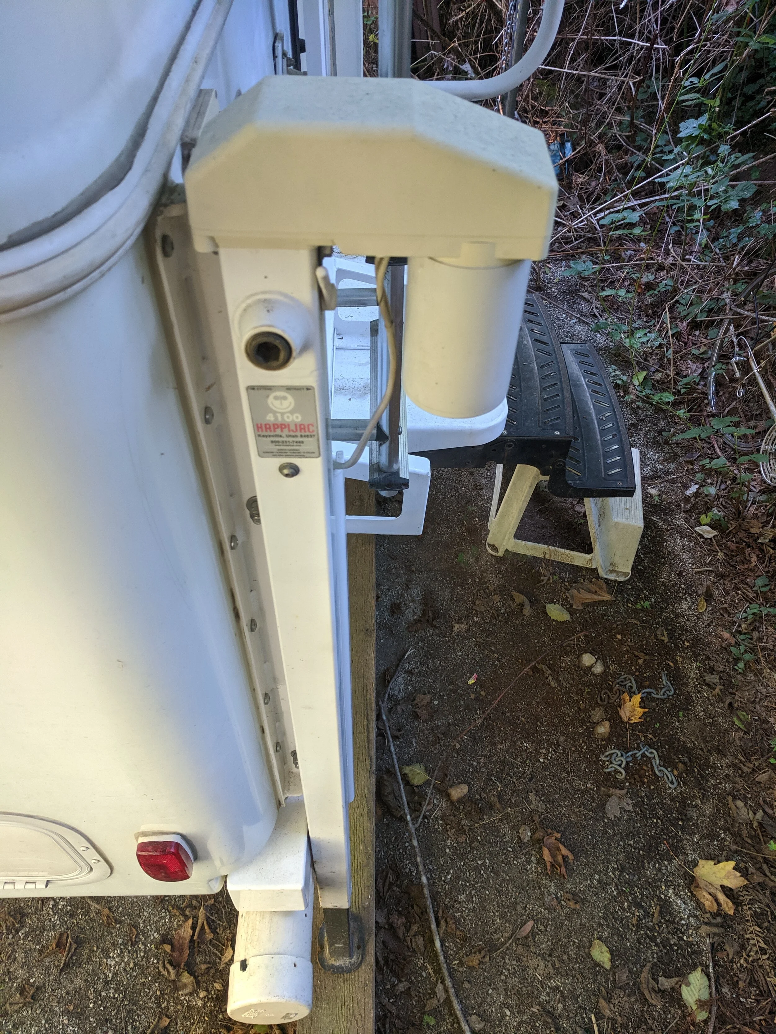
The Jacks
Each jack can be raised and lowered manually, or powered by a small 12V electric motor. The motor’s force is converted into linear movement with a geared worm-drive connection.
Electrically, all 4 jacks connect back to a control board, which is then directly connected to an auxiliary 12V lead-acid battery.

The Control Board
As you can see, a PCB made entirely with thru-hole components. Should be easy to figure out! The control board featured (note past tense) a Zilog Z80 processor from the 1970s (center) that received input commands via an “RJ-something” connector. The 4 ICs on the corners are NEC-ET2 dual relays, for connecting the motors in forward and reverse polarity. The top middle IC was completely unlabeled, but after some tracing I realized it was a relay driver, acting as a buffer between the Z80 and the relays. Eight pins in, eight pins out, I deduced it was a Darlington pair array and would need 8 GPIO signals from a micro-controller to function.
Also of note are the two bottom grey pieces, each a 15A fuse on the input terminals. This meant that only one motor could be driven at any given time.

Image Editing
I used the GNU Image Manipulation Program (GIMP) to reverse engineer the circuit. I took photos of the top and bottom, and resized them to match using the corner holes as references. Then, the bottom photo was reversed, so I could line up the pins of each IC and draw along the traces.
Top traces are shown in red, and bottom in blue.

New Brains
In short, I ripped out the Z80 and replaced it with an ESP32 SoC.
From Wikipedia:
ESP32 is a series of low-cost, low-power system on a chip microcontrollers with integrated Wi-Fi and dual-mode Bluetooth. The ESP32 series employs a Tensilica Xtensa LX6 microprocessor in both dual-core and single-core variations and includes built-in antenna switches, RF balun, power amplifier, low-noise receive amplifier, filters, and power-management modules.
A little bit overkill, to say the least! But with a pricetag of $12, I figured it would be worth focusing my efforts on this for now, so I could reuse the software in future projects that might need a bit more horsepower.
Software Development Platform
The Arduino platform is great. It’s easy, fast, and accessible for beginners. There are many software libraries that are easy to find and compatible with all kinds of micro-controllers. The downside is that it adds another layer of abstraction separating the developer from the hardware, and it’s generally harder to dig and find out what’s going on behind the scenes.
For this project I wanted to be able to organize the software among several files, use a version control system, and an IDE that included syntax highlighting and code navigation, so I decided to move away from the Arduino IDE.
Compared to the Arduino IDE, I see PlatformIO as a step towards manageable software development.
Installed as an extension to Visual Studio Code, it encourages better software practices: separating code into multiple files, continuous integration, and unit testing.
My goal is to eventually start working closer to bare metal by using whatever utilities are offered by the manufacturer. But for now, this took less than 5 minutes to get started, so I can’t complain!
Software Design
One of the reasons I chose to use the ESP32 SoC is because it’s not only Wi-Fi enabled, but can act as a Wi-Fi Access Point. This means it puts out its own wireless network that you can connect to with your phone or computer.
Naturally, I didn’t reinvent any wheels. I scoured the web, found some similar projects, and made some decisions.
Most Arduino-based projects implement a web server by hard-coding HTML into their source files. Maybe this would have been OK in the 90s, but it’s 2019 and I wanted a "web app", not a tangle of unmanageable source code. So I found a few projects that used AJAX and WebSockets to establish an on-going conversation between client and web server.
Software Test + Integration
One of the tricks with embedded web design is that the design-test cycle can take some time if you have to upload your code to the device with every iteration. So I used a Node.JS server to act as the ESP32 while doing all the web development. Then the design-test cycle was instantaneous.
Another thing that takes time is testing the device in the field. I found a few bugs with the system during this process, and realized it would be a lot faster if I could update its firmware wirelessly. So I did that.
Safety
Controlling the jacks of an RV can be pretty serious. If put enough out of level, it could roll and cause some damage and injury. I added a couple features to minimize this risk.
I called the stop command before every other command. This also had the nice side effect that only one jack could be activated at once.
I monitored the number of devices connected to the Wi-Fi network, and automatically shut off all jacks whenever there were no devices connected.

User Interface
I chose to use a web-based user interface so that the project was device-independent. No installation, just connect and go. It’s written using basic web tools: HTML/CSS and JavaScript. I used JSON to pass messages to/from the ESP32 using a WebSocket connection. This way, the controller could provide feedback in case something went wrong.
As you can see from the image, it’s nothing fancy. Buttons to activate each control.
Source Control
I used Git for source control, and put it all up on my personal account: